No products in the cart.

iMod Modules New
Introduction
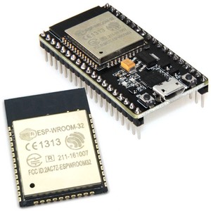
iMod Modules are small breakout boards that provide interface or I/O functionality.They have two rows of pin headers spaced 0.7" (or 0.9" for some larger modules) apart, allowing them to be mounted on a breadboard or standard 0.1" grid prototype board. They are however designed to plug into iMod ports, that are located on many Modtronix and Netcruzer board - click here for a list of board with iMod ports.
They are available with different pin headers, allowing them to be used for many applications.
The module normally has press-fit connectors, and can be pressed into the pads on the iMod Port without any solder required. For a permanent connection, it could also be soldered. It is part of the Modtronix Presto Range of products. An iMod Module is used to add functionality to a target board. Some typical iMod Modules have interface drivers for adding an interface to a target board, like RS-232, RS-485, CAN Bus...
Some text |
Some text |
Some text |
| Click to enlarge | ||

Description
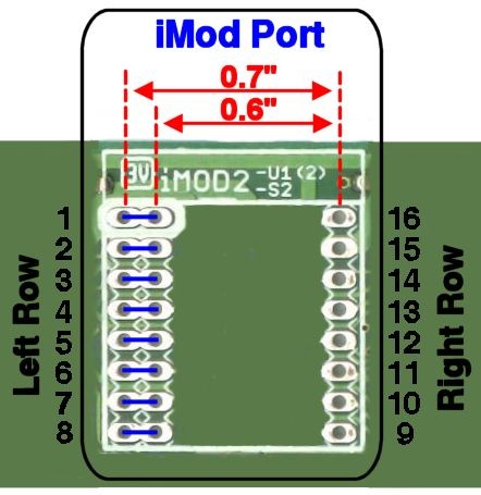
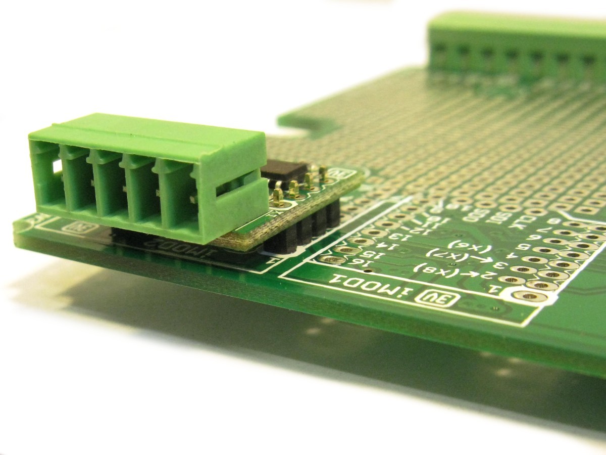
All iMod Modules have two rows of connectors, a left and a right row. The signals on these connectors are pre-defined, allowing modules to be interchangeable. On the iMod Port, pin 1 (top most pin) of the left row will have a white marking around it. Most iMod Ports will have multiple left and right rows, situated next to each other. This allows iMod Modules of different widths to be mounted. The first picture below shows a typical iMod Port with two left rows, and a single right row. This allows iMod Modules of 0.6" and 0.7" to be mounted. If an iMod Port has multiple left or right rows, the adjacent pads are connected, as shown (with blue lines) in this picture.
A single iMod Module is defined to have a maximum row spacing of 0.7”, referred to as one module width. Modules can however be wider than one module width, other common module widths are 0.9”, 1.1” and 1.6”. Target boards can provide iMod Ports for fitting iMod modules. An iMod Port is very simple and cheap to implement, only two rows of 1.00mm pads 0.7” apart are required (with a 0.1”, that is 2.54mm, grid). Modules wider than 0.7” will normally take up two iMod Ports on the target board. Adjacent iMod Ports should be spaced 0.2” apart. To help inserting the iMod module correctly into the iMod Port, pin 1 of the left connector is marked (white band around pad) on the iMod Module and iMod Port, and should always be aligned!
Some text |
Some text |
Some text |
| Click to enlarge | ||


iMod Port Pins
| The pins of an iMod Port are assigned standard signals: | ||||||||||||||||||||||||||||||||||||||||
| ||||||||||||||||||||||||||||||||||||||||
Multiple left or right rows
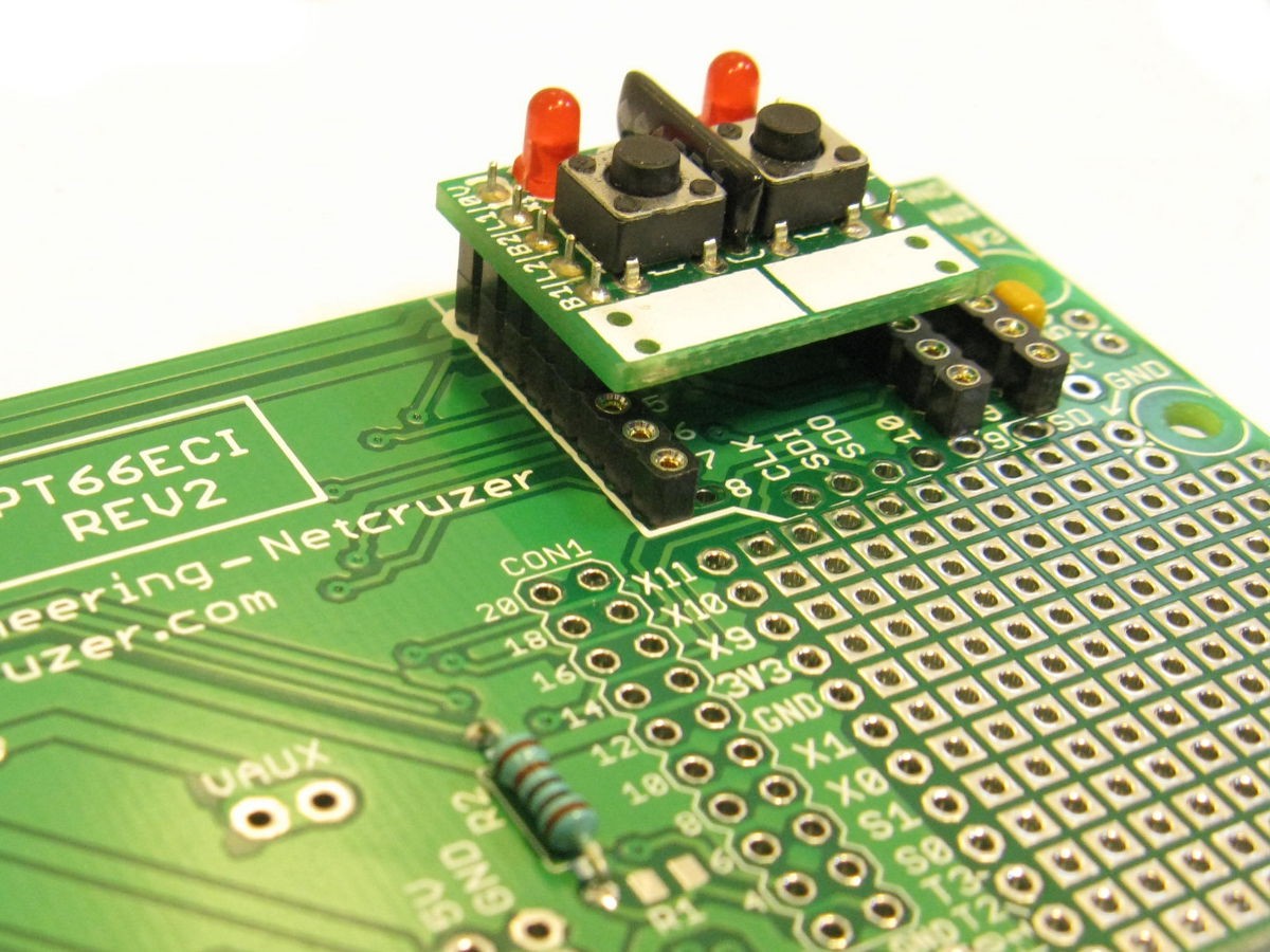
Most iMod Ports will have multiple left and right rows, situated next to each other. This allows iMod Modules of different widths to be mounted. The pictures below show some typical iMod Ports with multiple left and/or right rows. This allows iMod Modules of different widths to be mounted.
If an iMod Port has multiple left or right rows, the adjacent pads are electrically connected. This is shown with blue lines in the pictures below.
Shows iMod module with two left rows. This allows iMod Modules of 0.6" and 0.7" to be mounted. |
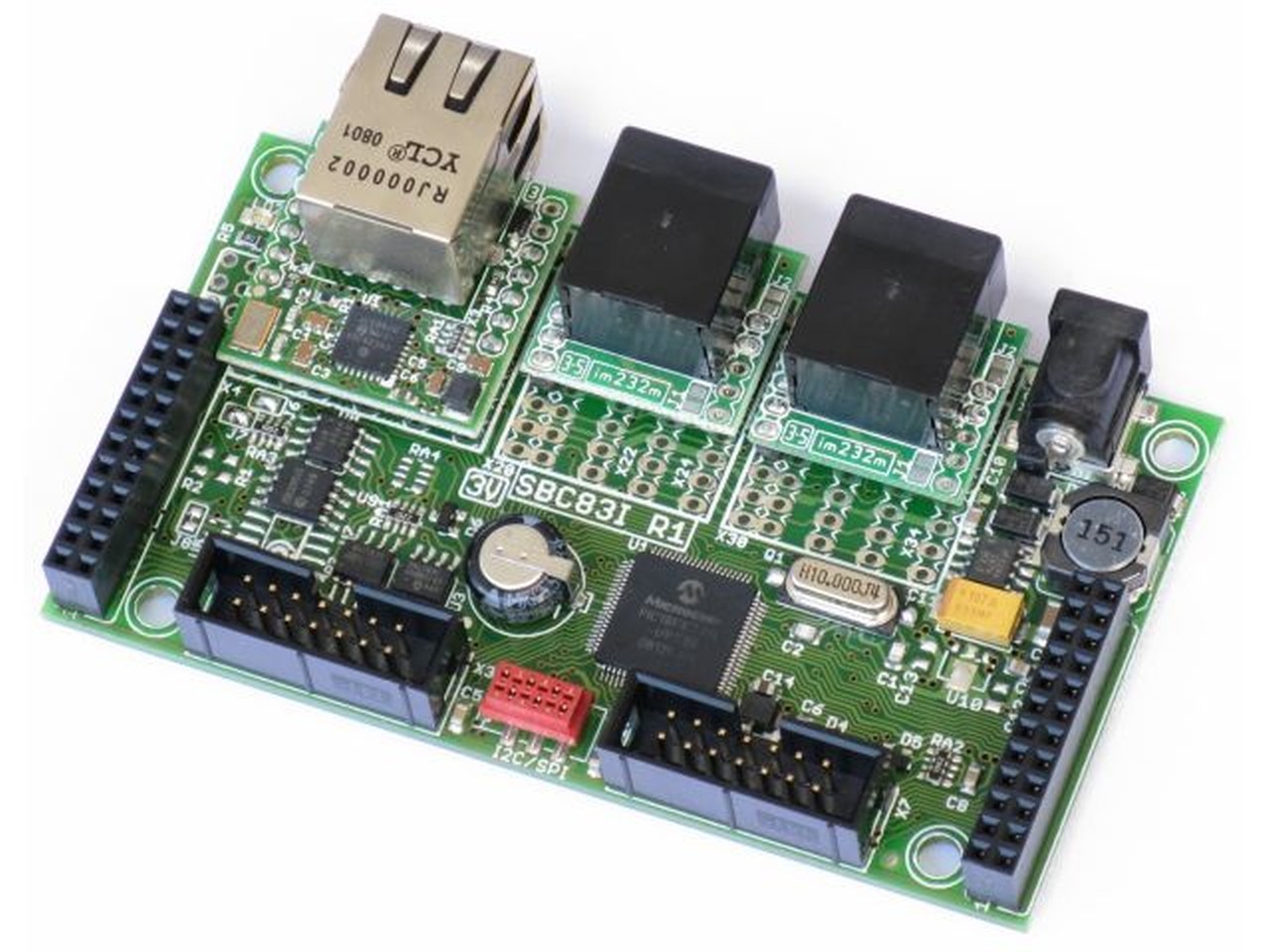
Shows a SBC board with 3 iMod Ports. The first port is 0.9" wide, and the other two the standard 0.7". Because each port has multiple left and right rows, iMod Modules of different widths can be fitted. |
| Click to enlarge | |