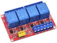
Relay Module, 2 Channels, 12V 10A Opto Isolated
Out of stock
$4.90
Discount per Quantity
| Quantity | Price |
|---|---|
| 1 | $4.90 |
| 2+ | $4.66 |
| 5+ | $4.41 |
| 10+ | $4.17 |
| 20+ | $3.92 |
Out of stock
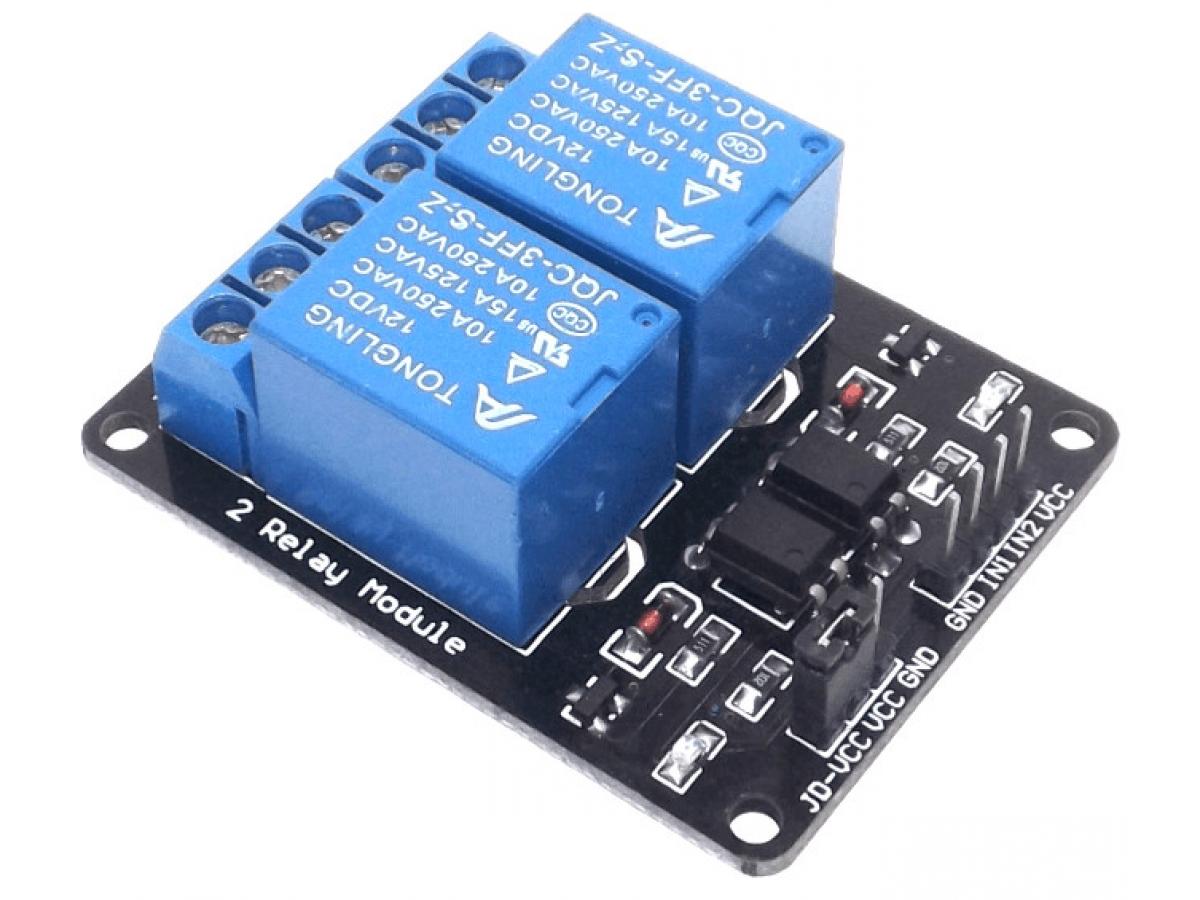
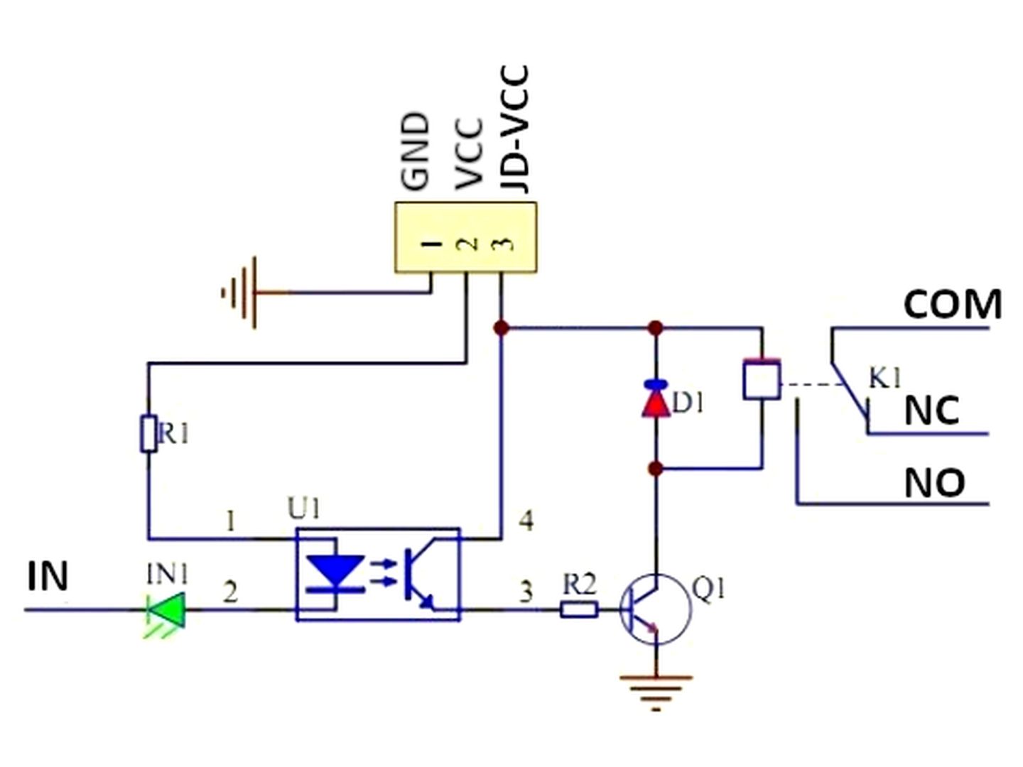
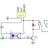
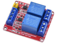
This modules contains 2 relays, rated at 12V and 10A. Each relay has a LED indicator. It can be used to control various appliances, and other equipment with large current. Each relay has an Optocoupler, providing optical isolation. Each relay also have a freewheeling diode protection. This module has a 4 pin header(standard 2.54mm pitch) for connecting power (12V and GND), and controlling the relays. These pins have the following functions:
-
IN1 to IN2: Controls relays 1 to 2, active Low! Relay will turn on when this input goes below about 2.0V
-
GND: Connect 0V to this pin. Is used to power the board (optocouplers and relays)
-
VCC: Connect 12V to this pin. Is used to power the board (optocouplers and relays)
There is a second 1×3 (2.54mm pitch) pin header for supplying the “relay side” of the board with 12V. At delivery, a jumper is present on this header selecting the 12V signal from main pin header to power the relays. For default operation, don’t change this jumper!
The pins of the 1×3 pin header are marked on the PCB:
- JD-VCC – This is the 12V required for the relays. At delivery, a jumper is present on this and the adjacent (VCC) pin
- VCC – This is the 12V VCC supplied on the main pin connector
- GND – Connected to 0V pin of main pin header
For liability and safety reasons we DO NOT recommend using this module with voltages above 24V. Any use of this module is at your own risk! Always take necessary safety precautions when working with high voltages to prevent electrical shock! We will take no responsibility for any damage, personal injury or death incurred due to using this unit with high voltages!
Please note: The relays used are normally Hongfa(JQC), Songle or Tongling, which are all good quality and have the same specifications. During shipping to us from Asia, these modules some times get small scratches on top of the relays (from the other boards rubbing against them).
Please note these are VERY LOW cost boards from China. If you expect a premium product, this is NOT for you. These boards might have scratches on them, might not be the cleanest, and the packaging might have scratches or small tears. For example, if the board has pin headers, they are often ship to us from China all together in a bag, and the pins might be slightly bent or protrude through the bag. If this is not acceptable, please look for a more premium product. After all our costs (10% GST, over 10% eBay/PayPal fee and "Free" shipping we have to pay for), you can appreciate that there is very, very little profit margin left for us. We bring you these products at a very good price, but keep in mind it is a very low cost, cheap and nasty cheap product - exactly the same as similar price products sold by other sellers.Low voltage control
The relays can be controlled directly with a 3.3V or 5V logic signals. For example, from a microcontroller like Arduino, 8051, AVR, PIC, DSP, ARM, ARM, MSP430, TTL logic). For this mode of operation, connect the board as follows:
- Connect the VCC and GND pins on the 4 pin header to the low voltage(3.3V or 5V) supply that will be controlling the relays(from Arduino board for example)
- Remove the jumper on the small 3 pin header
- Connect the GND and JD-VCC pins on the small 3 pin header to 12V supply. This is used for the relays.
The relays can now be controlled with a low voltage signal, for example from a port pin of a 3.3V or 5V microcontroller.
Specifications
-
Channels: 2 Relays
-
Relay Voltage: 12V
-
Relay Coil Current: 32mA at 12V per relay
-
Relay Output Current: 10A at 250VAC, 10A at 30VDC
-
Board Supply: 12V supply voltage
-
Input Type: Opto Isolated inputs
-
Power LED: 1 LED for power indication
-
Channel LEDs: 2 LEDs to indicate state of each relay
-
Module dimension: 50.6mm x 39mm
Package Includes
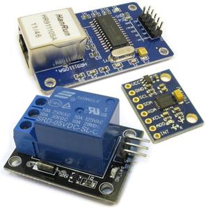
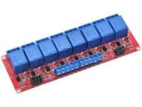
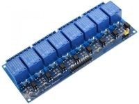
1 x Relay modules, 2 relays (as shown in picture)
| Weight | 30 g |
|---|---|
| Dimensions | 15 × 15 × 5 cm |
| Voltage | 12V |

