No products in the cart.
ESP32 & ESP8266, WiFi Modules
ESP-WROVER-KIT VB, ESP32, LCD, WiFi, Bluetooth, USB, SD Card
Availability:
Out of stock
SKU: ESP3-002Code: ESP-WROVER-KIT
ESP-WROVER-KIT V3, ESP32, LCD, WiFi, Bluetooth, USB, SD Card
$79.00
Discount per Quantity
| Quantity | Price |
|---|---|
| 1+ | $79.00 |
| 5+ | $71.10 |
| 10+ | $67.15 |
| 20+ | $63.20 |
Out of stock
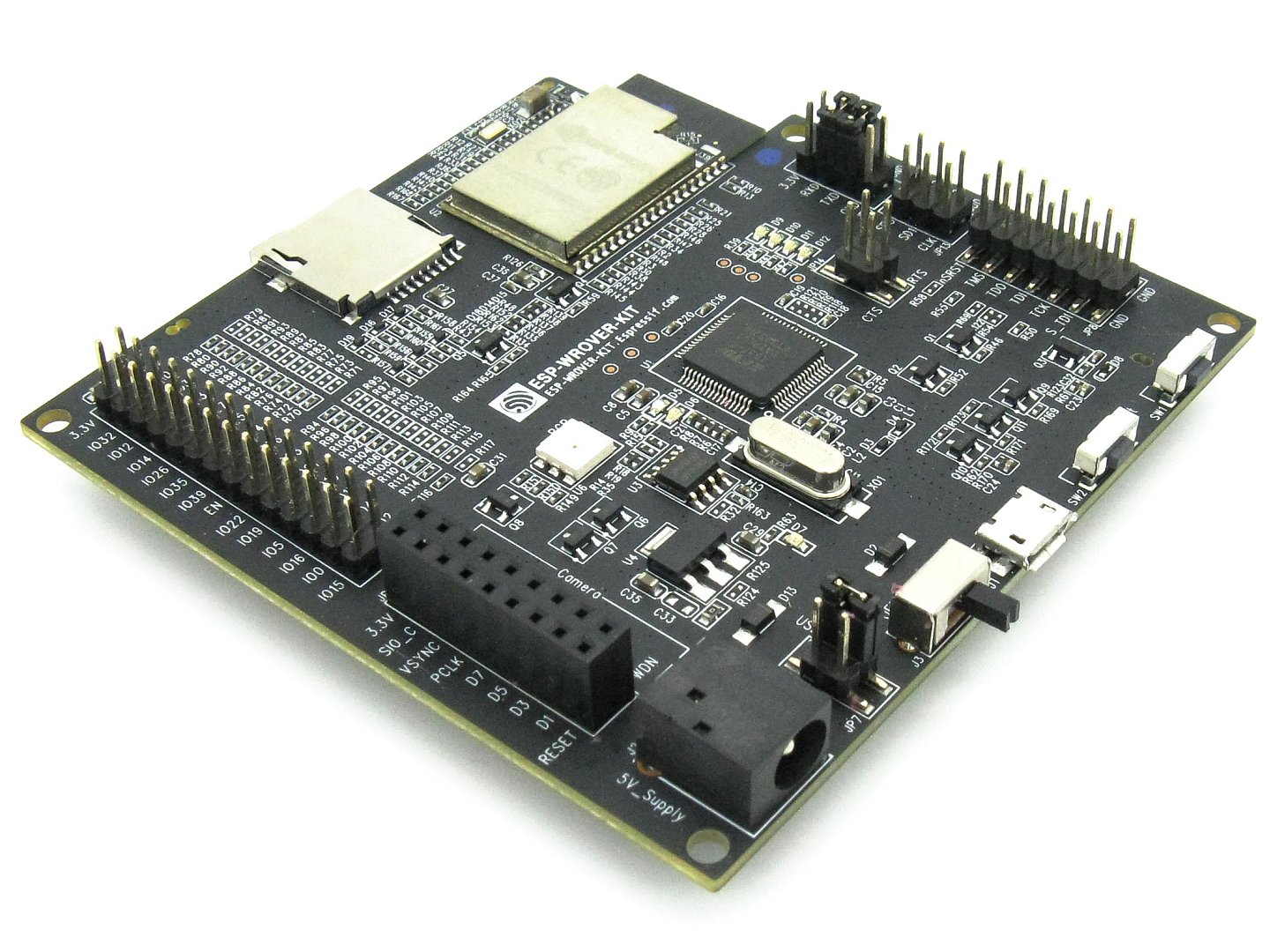
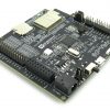
The ESP-WROVER-KIT-VB (ESP32-WROVER-KIT) is a development board produced by Espressif built around ESP32. This is the latest VB of this kit, direct from Espressif. The I/O pins have been broken out from the ESP32 module for easy extension. The board carries an advanced multi-protocol USB bridge (the FTDI FT2232HL), enabling developers to use JTAG directly to debug the ESP32 through the USB interface. The development board makes secondary development easy and cost-effective. The V3 kit is populated with the ESP32-WROVER module, which has a whopping 32Mbit(4 MByte) of FLASH, and 64Mbit (8MByte) RAM.
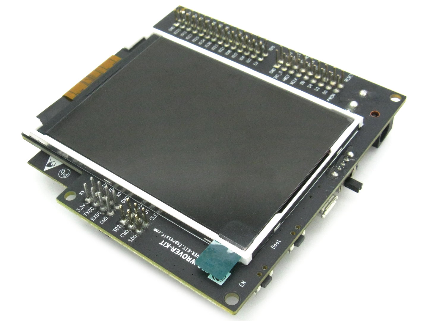
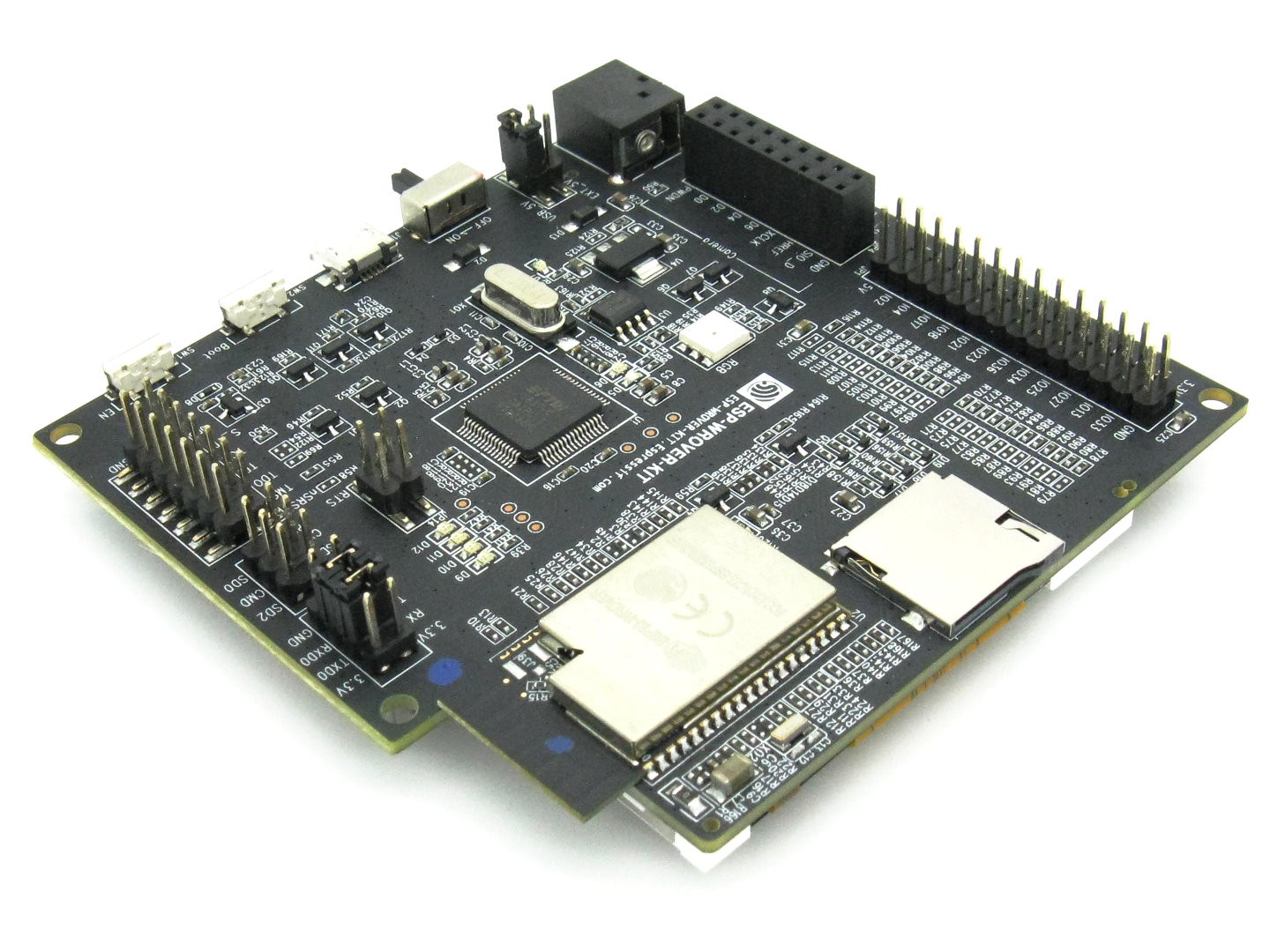
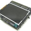
Please note the pictures are of the older V3 or the rover kit. See link below, or Google "ESP-WROVER-KIT-VB" to get info on this latest kit.
Compared to ESP-WROVER-KIT V3, this board has the following design changes:
- JP8, JP11, and JP13 have been combined into a single JP2.
- USB connector has been changed to DIP type and moved to the lower right corner of the board.
- R61 has been changed to a Zero-ohm resistor.
- Some components have been replaced with functional equivalents based on test results and
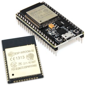
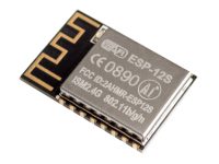
The ESP32 is a WiFi & Bluetooth module, using the popular ESPRESSIF ESP32 chip.
The ESP32 chip integrates a dual-core processor with 448 KByte ROM, 520 KByte SRAM, 16 KByte SRAM in RTC, 802.11 b/g/n/e/I Wi-Fi, Bluetooth v4.2 BR/EDR & BLE, clocks & Times, abundant peripheral Interfaces and sercurity mechanism. Additionally 32Mbit(4 MByte) of FLASH, and 64Mbit (8MByte) RAM is available via two external serial SPI chips.
Software can be developed using many different platforms, including Arduino. It is designed for Generic low power IoT sensor hub, loggers, video steaming for camera, Wi-Fi & Bluetooth enabled devices, Home automation and mesh network applications, aimed at makers, hardware engineers, software engineers and solution provides.
Documentation
For additional information, see the manufacturer's product page.product page:
espressif.com/en/products/hardware/esp-wrover-kit/overview
Wiki get start guide:
esp-idf.readthedocs.io/en/latest/get-started/get-started-wrover-kit.htmlesp-idf.readthedocs.io/en/latest/get-started/get-started-wrover-kit.html
ESP-32S
- CPU and Memory: Xtensa® 32-bit LX6 Dua-core processor, up to 600 DMIPS
- 4 MByte SPI Flash
- 448 KByte ROM
- 520 KByte SRAM
- 16 KByte SRAM in RTC
- On board 3DBi PCB antenna
- Compact size of 25.4mm x 48.3mm
WiFi
- 802.11 b/g/n/e/i
- 802.11 n (2.4 GHz), up to 150 Mbps
- 802.11 e: QoS for wireless multimedia technology.
- WMM-PS, UAPSD
- MPDU and A-MSDU aggregation
- Block ACK
- Fragmentation and Defragmentation
- Automatic Beacon monitoring/scanning
- 802.11 i security features: pre-authentication and TSN
- Wi-Fi Protected Access (WPA)/WPA2/WPA2-Enterprise/Wi-Fi Protected Setup (WPS)
- Infrastructure BSS Station mode/SoftAP mode
- Wi-Fi Direct (P2P), P2P Discovery, P2P Group Owner mode and P2P Power Management
- UMA compliant and certified
- Antenna diversity and selection
Bluetooth
- Compliant with Bluetooth v4.2 BR/EDR and BLE specification
- Class-1, class-2 and class-3 transmitter without external power amplifier
- Enhanced power control
- +10 dBm transmitting power
- NZIF receiver with -98 dBm sensitivity
- Adaptive Frequency Hopping (AFH)
- Standard HCI based on SDIO/SPI/UART ? High speed UART HCI, up to 4 Mbps
- BT 4.2 controller and host stack
- Service Discover Protocol (SDP)
- General Access Profile (GAP)
- Security Manage Protocol (SMP)
- Bluetooth Low Energy (BLE)
- ATT/GATT
- HID
- All GATT-based profile supported
- SPP-Like GATT-based profile
- BLE Beacon
- A2DP/AVRCP/SPP, HSP/HFP, RFCOMM
- CVSD and SBC for audio codec
- Bluetooth Piconet and Scatternet
Details
Functionality Overview
Block diagram below presents main components of ESP-WROVER-KIT and interconnections between components.

ESP-WROVER-KIT block diagram
Functional Description
The following list and figures below describe key components, interfaces and controls of ESP-WROVER-KIT board.
32.768 kHz:
An external precision 32.768 kHz crystal oscillator provides the chip with a clock of low-power consumption during the Deep-sleep mode.
OR
A zero Ohm resistor intended as a placeholder for a current shunt. May be desoldered or replaced with a current shunt to facilitate measurement of current required by ESP32 module depending on power mode.ESP32 Module ESP-WROVER-KIT is compatible with both ESP-WROOM-32 and ESP32-WROVER. The ESP32-WROVER module features all the functions of ESP-WROOM-32 and integrates an external 32-MBit PSRAM for flexible extended storage and data processing capabilities.
Note: GPIO16 and GPIO17 are used as the CS and clock signal for PSRAM. To ensure reliable performance, the two GPIOs are not broken out.
FT2232:
The FT2232 chip is a multi-protocol USB-to-serial bridge. Users can control and program the FT2232 chip through the USB interface to establish communication with ESP32. The FT2232 chip also features USB-to-JTAG interface. USB-to-JTAG is available on channel A of FT2232, USB-to-serial on channel B. The embedded FT2232 chip is one of the distinguishing features of the ESPWROVER-KIT. It enhances users’ convenience in terms of application development and debugging. In addition, users do not need to buy a JTAG debugger separately, which reduces the development cost, see ESP-WROVER-KIT V3 schematic.
UART:
Serial port: the serial TX/RX signals on FT2232HL and ESP32 are broken out to the two sides of JP11. By default, the two signals are connected with jumpers. To use the ESP32 module serial interface only, the jumpers may be removed and the module can be connected to another external serial device.
SPI:
SPI interface: the SPI interface connects to an external flash (PSRAM). To interface another SPI device, an extra CS signal is needed. The electrical level on the flash of this module is 1.8V. If an ESP-WROOM-32 is being used, please note that the electrical level on the flash of this module is 3.3V.
CTS/RTS:
Serial port flow control signals: the pins are not connected to the circuitry by default. To enable them, respective pins of JP14 must be shorted with jumpers.
JTAG:
JTAG interface: the JTAG signals on FT2232HL and ESP32 are broken out to the two sides of JP8. By default, the two signals are disconnected. To enable JTAG, shorting jumpers are required on the signals.
EN:
Reset button: pressing this button resets the system.
Boot:
Download button: holding down the Boot button and pressing the EN button initiates the firmware download mode. Then user can download firmware through the serial port.
USB:
USB interface. It functions as the power supply for the board and the communication interface between PC and ESP32 module.
Power Select:
Power supply selection interface: the ESP-WROVER-KIT can be powered through the USB interface or the 5V Input interface. The user can select the power supply with a jumper. More details can be found in section Setup Options, jumper header JP7.
Power Key:
Power on/off button: toggling to the right powers the board on; toggling to the left powers the board off.
5V Input:
The 5V power supply interface is used as a backup power supply in case of full-load operation.
LDO:
NCP1117(1A). 5V-to-3.3V LDO. (There is an alternative pin-compatible LDO — LM317DCY, with an output current of up to 1.5A). NCP1117 can provide a maximum current of 1A. The LDO solutions are available with both fixed output voltage and variable output voltage. For details please refer to ESP-WROVER-KIT V3 schematic.
Camera:
Camera interface: a standard OV7670 camera module is supported.
RGB:
Red, green and blue (RGB) light emitting diodes (LEDs), which may be controlled by pulse width modulation (PWM).
I/O:
All the pins on the ESP32 module are led out to the pin headers on the ESP-WROVER-KIT. Users can program ESP32 to enable multiple functions such as PWM, ADC, DAC, I2C, I2S, SPI, etc.
Micro SD Card:
Micro SD card slot for data storage.
LCD:
ESP-WROVER-KIT supports mounting and interfacing a 3.2” SPI (standard 4-wire Serial Peripheral Interface) LCD, as shown on figure ESP-WROVER-KIT board layout - back.

Package Includes
1 x Development Kit, VB version

