No products in the cart.
ESP32 & ESP8266, WiFi Modules
ESP32-S3-DevKitC-1U-N8R8 Development Board, ESP32-S3-WROOM-1U, U.FL
Availability:
Out of stock
SKU: ESP3-035Code: ESP32-S3-DEVKITC-1U-N8R8
$29.90
Discount per Quantity
| Quantity | Price |
|---|---|
| 1+ | $29.90 |
| 5+ | $26.91 |
| 10+ | $25.42 |
| 20+ | $23.92 |
Out of stock
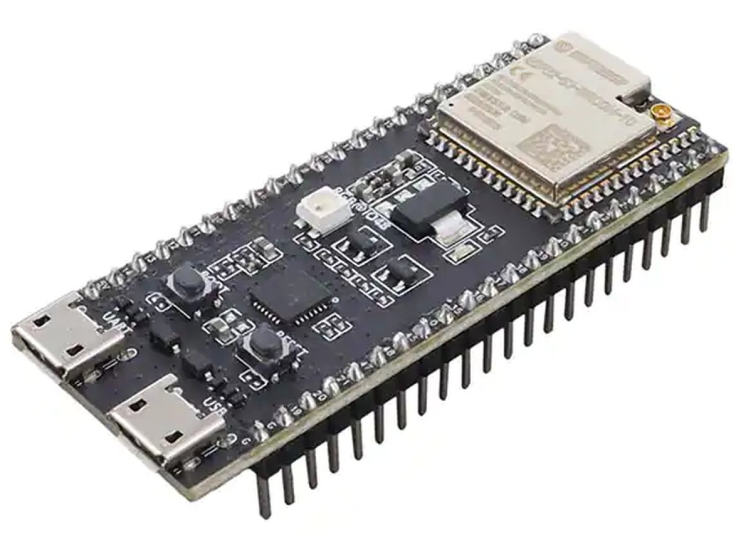
The ESP32-S3-DevKitC-1 is an entry-level development board equipped with the ESP32-S3-WROOM-1U, a general-purpose Wi-Fi + Bluetooth® LE MCU module that integrates complete Wi-Fi and Bluetooth LE functions.
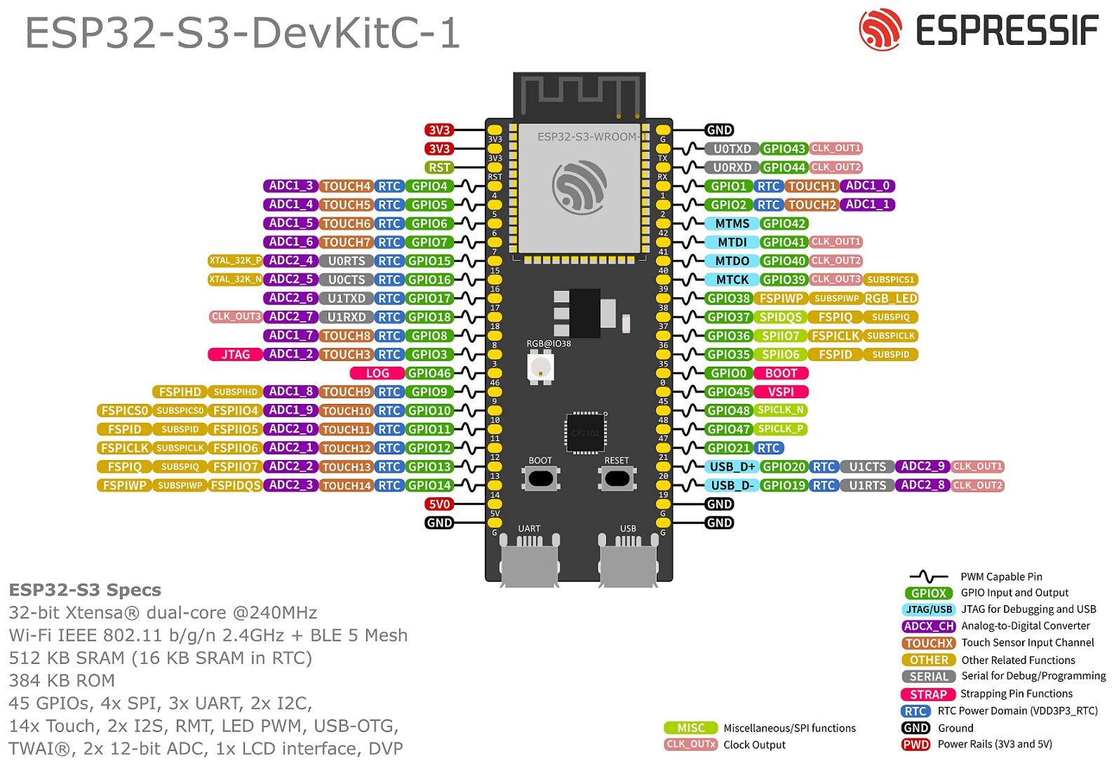
Most of the I/O pins on the module are broken out to the pin headers on both sides of this board for easy interfacing. Developers can either connect peripherals with jumper wires or mount ESP32-S3-DevKitC-1 on a breadboard.
To view user guide on the manufacturer's site, click here.see this page:
docs.espressif.com/projects/esp-idf/en/latest/esp32s3/hw-reference/esp32s3/user-guide-devkitc-1.html
The ESP32-S3 is a dual-core XTensa LX7 MCU, capable of running at 240 MHz. Apart from its 512 KB of internal SRAM, it also comes with integrated 2.4 GHz, 802.11 b/g/n Wi-Fi and Bluetooth 5 (LE) connectivity that provides long-range support. It has 45 programmable GPIOs and supports a rich set of peripherals. ESP32-S3 supports larger, high-speed octal SPI flash, and PSRAM with configurable data and instruction cache.
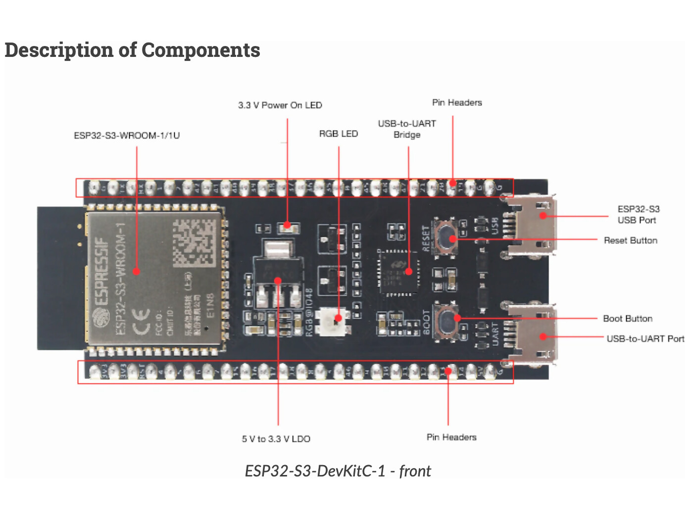
Key Component | Description |
|---|---|
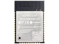
ESP32-S3-WROOM-1/1U/2 | ESP32-S3-WROOM-1, ESP32-S3-WROOM-1U, and ESP32-S3-WROOM-2 are powerful, generic Wi-Fi + Bluetooth LE MCU modules that have a rich set of peripherals. They provide acceleration for neural network computing and signal processing workloads. ESP32-S3-WROOM-1 and ESP32-S3-WROOM-2 comes with a PCB antenna. ESP32-S3-WROOM-1U comes with an external antenna connector. |
5 V to 3.3 V LDO | Power regulator that converts a 5 V supply into a 3.3 V output. |
Pin Headers | All available GPIO pins (except for the SPI bus for flash) are broken out to the pin headers on the board for easy interfacing and programming. For details, please see Header Block. |
USB-to-UART Port | A Micro-USB port used for power supply to the board, for flashing applications to the chip, as well as for communication with the chip via the on-board USB-to-UART bridge. |
Boot Button | Download button. Holding down Boot and then pressing Reset initiates Firmware Download mode for downloading firmware through the serial port. |
Reset Button | Press this button to restart the system. |
ESP32-S3 USB Port | ESP32-S3 full-speed USB OTG interface, compliant with the USB 1.1 specification. The interface is used for power supply to the board, for flashing applications to the chip, for communication with the chip using USB 1.1 protocols, as well as for JTAG debugging. |
USB-to-UART Bridge | Single USB-to-UART bridge chip provides transfer rates up to 3 Mbps. |
RGB LED | Addressable RGB LED, driven by GPIO38. |
3.3 V Power On LED | Turns on when the USB power is connected to the board. |
Features
- 2.4 GHz Wi-Fi, EEE 802.11 b/g/n-compliant
- Bluetooth, LE: Bluetooth 5, Bluetooth mesh
- 8 MByte(64Mbit) SPI Flash
- 384 KByte ROM
- 512 KByte SRAM
- 16 KB SRAM in RTC
- Dual Micro USB connectors
- Reset and User/Firmware buttons
- User and Power LED
- Virtual USB port provided by CP2102 for debugging and firmware upgrade
- Compact size of 50.1 x 13mm
- Supply Voltage: 5V via USB, 3.3V Circuit Operation
Package Includes
1 x ESP32 DevKitC
| Weight | 10 g |
|---|---|
| Platform | |
| Brand | |
| Wired Technology | |
| Flash Memory | |
| External RAM | |
| Chip Family | |
| Connector |

